
New Six Robot Welding Cell Produces 45% Improvement in Cycle Time
- drewfinncam8
- Feb 21, 2024
- 4 min read

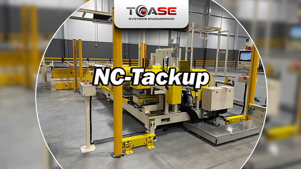
The robot welding cell as it was set up in our facility prior to customer install
TOA SE has had a busy December 2023 shutdown and it was capped off with the successful installation of a large, six robot welding cell.
In early 2023, we were awarded a project by one of our biggest customers to replace an aging robotic weld cell that welded machined pins onto metal plates. This fabricated part is a critical component of a forklift mast assembly. Welding associates had to manually place the correct pins in place on the plate and tack the pins in place before placing them on a buffer conveyor that fed into the cell. From there, the welding robot completed the full weld on the pins. This single robot cell was no longer able to keep up with increased production.
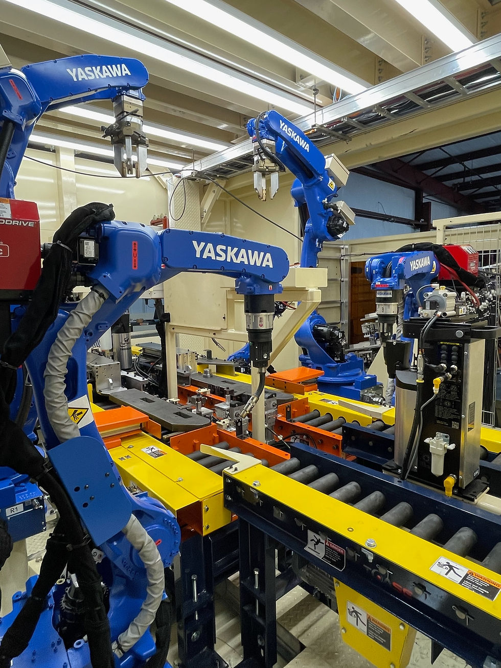
An interior view of the robotic welding cell
The goal for the new upgraded weld cell was to improve cycle time by automating pin placement on the plates, decrease the time needed to weld the pins by increasing the number of welding robots, and improving weld quality by using updated welding robots and by preheating the pins using an induction heater.
The new pin welding cell was able to accomplish all these objectives with a custom engineered and fabricated common base cell with a mezzanine to hold all robotic, welding, and controls equipment. The cell contains a large sliding door for service access and a man door. Some of the equipment includes four Yaskawa Motoman® AR1440 welding robots with Lincoln welders, two Motoman GP25 material handling robots, Cyprium induction heater, custom Omni powered conveyor, Omron NX PLC controls, and a fully custom pin feeding system that uses Keyence IX sensors to pokayoke the pin feeding system. With twenty-two different plates and eleven different pins, this welding cell can process 120-part types. This upgraded system has resulted in a 45% improvement in the cycle time.
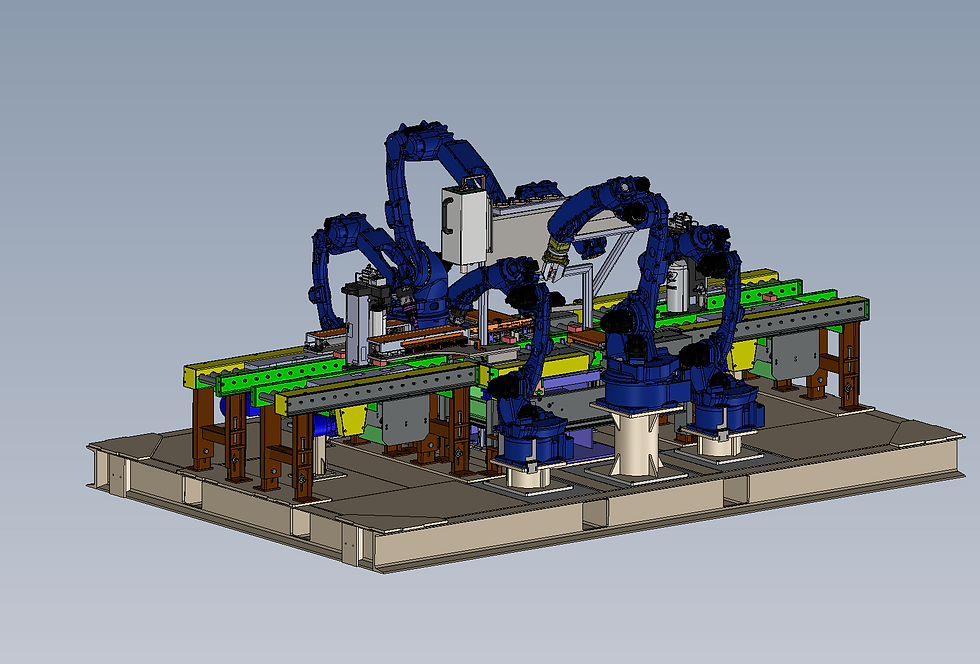
SolidWorks drawing of the cell base with conveyors, robots, and induction heater
The robot teaching was done by creating a user frame in the robots using a Master Plate to reference 0,0,0 on the Conveyor. This Origin coincided with the origin on all Parts Drawings, thus calibrating the Robots to the X/Y/Z Pin Locations found in the customer drawings. A Database was created with part-specific information including these Pin X/Y/Z locations, as well as what Weld Program to use and other pertinent information. When a part is loaded into the machine, a Barcode queries this Database, and sends the appropriate Part Data to the Robots.
This setup makes the system very dynamic, and greatly reduced commissioning time by only requiring the teaching of a User Frame, instead of teaching hundreds of different Pin locations for the various parts. It also increases up-time, as any changes don’t need full Robot re-teaching, just a simple update of the User Frame location. In addition, new Part Types can be added to the Database and run in production immediately, as opposed to teaching them individually in the Robots.

Main control panel for the cell that was mounted on the mezzanine
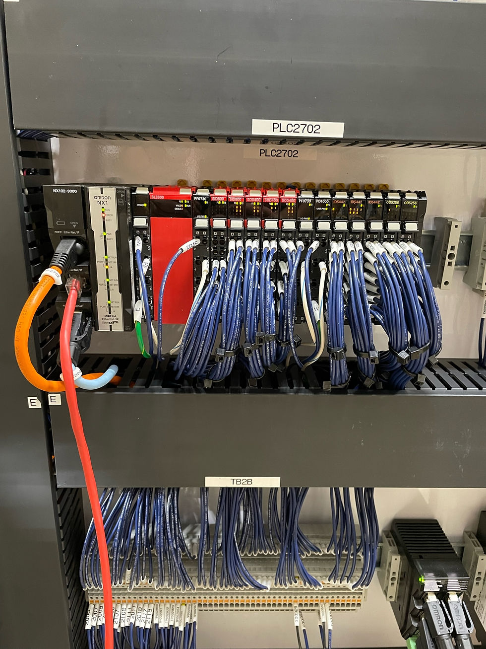
The Omron NX102 PLC is the brains behind the control system
The cell operation starts with an associate placing plates on a gravity conveyor based on the planned production. The associate scans in each plate using a Keyence barcode scanner into the Omron NA HMI. The conveyor system brings in two plates at a time on two separate lanes, a left hand and right-hand plate. In the meantime, one of the GP25 material handling robots will grab pins from the custom pin feeding system. The pin feeding system has eleven gravity roller lanes for each pin model. The pin feeding system has a pokayoke system to prevent the associate from putting pins in the wrong lane using Keyence IX sensors that are located at each lane entrance. Multiple prox sensors are used in each lane to track pin quantities. The material handling robot is equipped with custom tooling mounted to a Schunk 3 finger gripping unit. The custom tooling consists of PEEK isolation pads, aluminum fingers, and brass contact pads to not damage the machined surface of the pins.

Detail of robot gripper
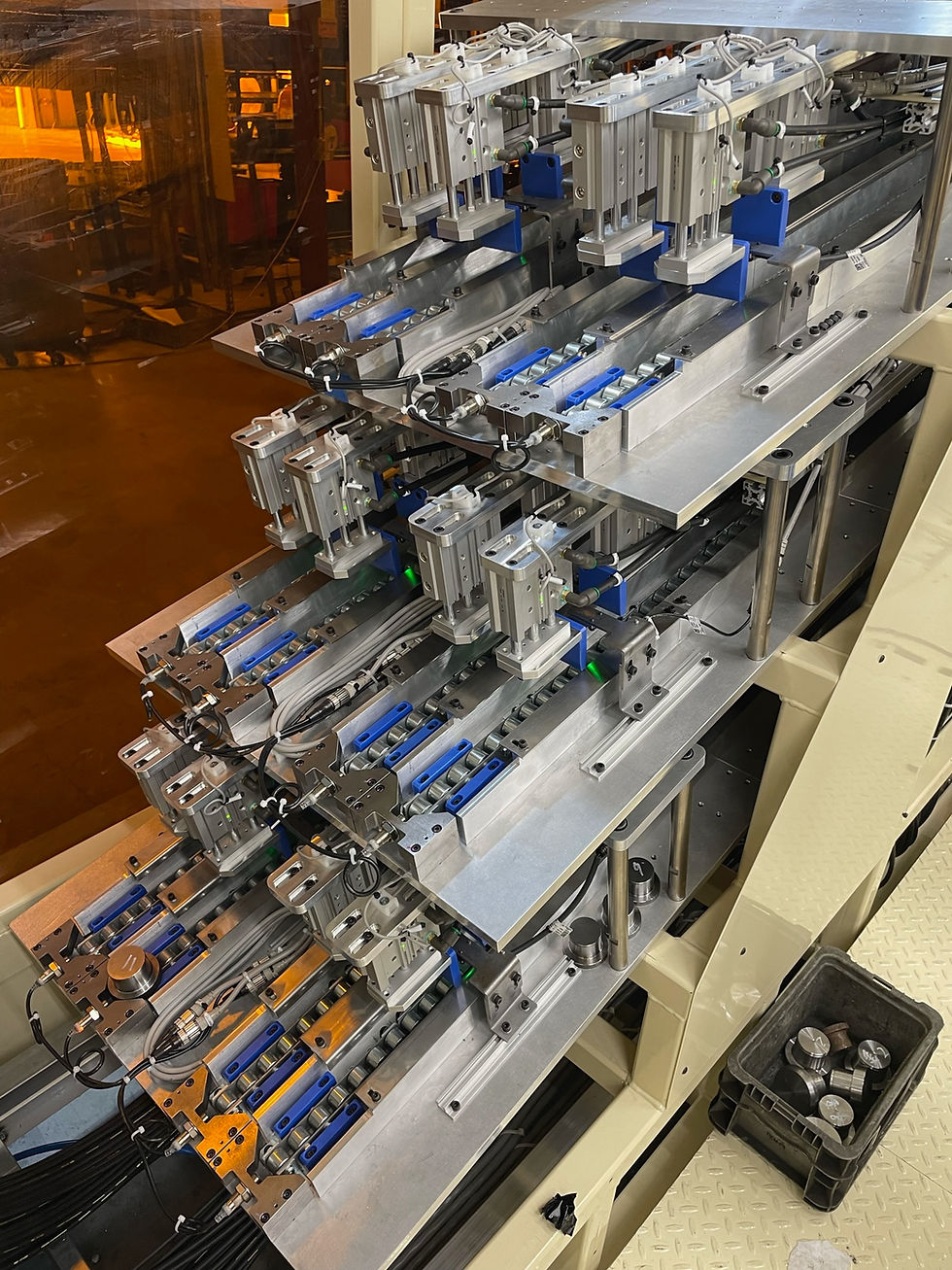
Custom automated pin feeding system
The pins are placed in an induction heater coil located between the two conveyor lanes where they get heated up to the target temperature in a matter of seconds. Once the pins are preheated, both GP25 robots will pick and place the pins into the correct position on the plates. The pins are held in place while the welding robots come in and tack the pins to the plates, before the GP25 robot releases the pins and the welding robots complete their full weld. Once the welds are completed, the two conveyors will transfer the completed parts out of the cell.
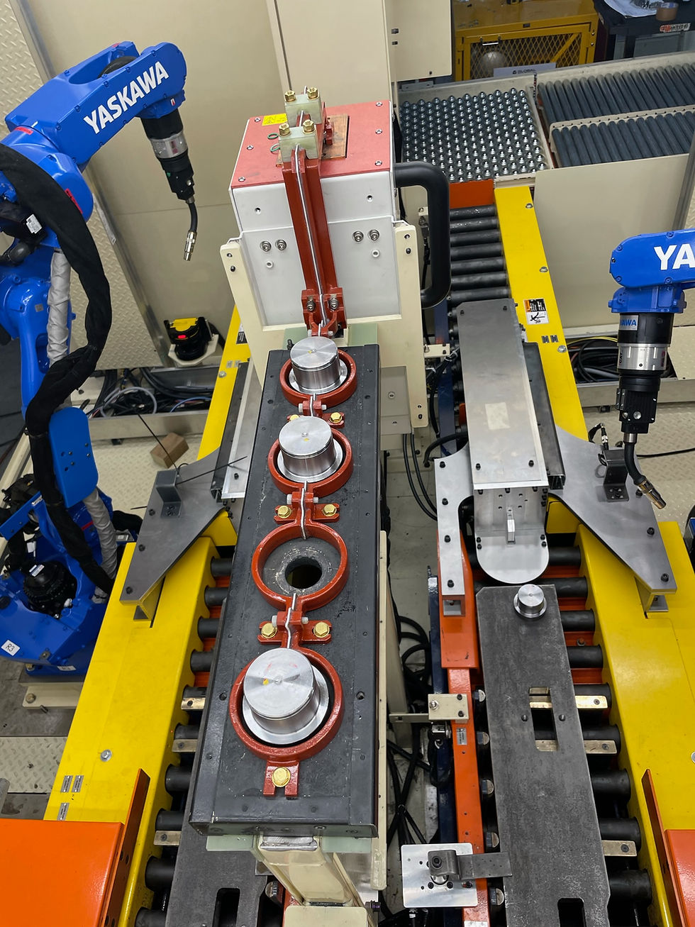
Pins sitting in the induction heater coils.
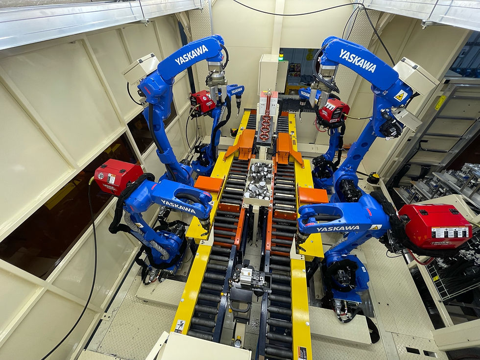
Overhead view of the inside of the welding cell
Sam Trammell, the engineer from the customer who awarded TOA SE this project, had this to say following the successful installation of the cell: “While working with TOA I enjoyed the responsiveness of their sales and engineering team. I also appreciated their open-mindedness to new concepts and changes that occurred throughout the project. In all respects of the project TOA embraced new ideas and challenges to provide and exceptional product that precisely met the customers' need”.

Welding cell successfully running at the customer's plant.
TOA SE is grateful to be given the opportunity to deliver a complex project such as this. If you are looking for an experienced systems integrator to help solve your automation needs, we are willing and capable to take on the challenge. Feel free to reach out to us!


Comments